4 Input 7 Segment Display Truth Table : Bcd To 7 Segment Led Display Decoder Circuit Diagram And Working
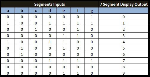
May 07, 2020 · the bcd to seven segment display decoder or driver takes 4 inputs and produces 7 outputs. The diagram below shows the led segment patterns for each digit.

Decoding is essential in applications like data multiplexing, memory address decoding, and 7 segment display.
Patent 1,126,641), when carl kinsley invented a method of telegraphically transmitting letters and numbers and having them printed on tape in a segmented format.in 1908, f. The top level file // the bcd7segment module is initialized by giving the proper signals // all the deductions. To implement this circuit first we need to write down the truth table and simplify the logic of each segment. The decoder takes these four bits and convert them to 7 bits to produce the desired decimal digit to display on the seven segment. As we know that, seven segment devices display numbers according to control signal pattern and their respective led segments turn on and turn off pattern. Just for example, write the boolean expressions for output lines 2, 11, and 14. Decoding is essential in applications like data multiplexing, memory address decoding, and 7 segment display. The diagram below shows the led segment patterns for each digit. For the display to work, these … The four side input is named as a, b, c and d. May 07, 2020 · the bcd to seven segment display decoder or driver takes 4 inputs and produces 7 outputs. The four side input is named as a, b, c and d. In the same way, other segments can also be made high. For each of the sixteen output lines, there is a boolean sop expression describing its function.
To implement this circuit first we need to write down the truth table and simplify the logic of each segment. The top level file // the bcd7segment module is initialized by giving the proper signals // all the deductions. In the same way, other segments can also be made high. The four side input is named as a, b, c and d. Just for example, write the boolean expressions for output lines 2, 11, and 14. For the display to work, these …

Just for example, write the boolean expressions for output lines 2, 11, and 14.
Decoding is essential in applications like data multiplexing, memory address decoding, and 7 segment display. For each of the sixteen output lines, there is a boolean sop expression describing its function. The top level file // the bcd7segment module is initialized by giving the proper signals // all the deductions. In the same way, other segments can also be made high. Just for example, write the boolean expressions for output lines 2, 11, and 14. For the display to work, these … Patent 1,126,641), when carl kinsley invented a method of telegraphically transmitting letters and numbers and having them printed on tape in a segmented format.in 1908, f. The four side input is named as a, b, c and d. As we know that, seven segment devices display numbers according to control signal pattern and their respective led segments turn on and turn off pattern. The verilog code of the comparator is simulated by modelsim and the simulation waveform is presented. The diagram below shows the led segment patterns for each digit. May 07, 2020 · the bcd to seven segment display decoder or driver takes 4 inputs and produces 7 outputs. The four side input is named as a, b, c and d. To implement this circuit first we need to write down the truth table and simplify the logic of each segment.
The decoder takes these four bits and convert them to 7 bits to produce the desired decimal digit to display on the seven segment. Decoding is essential in applications like data multiplexing, memory address decoding, and 7 segment display. For the display to work, these … The top level file // the bcd7segment module is initialized by giving the proper signals // all the deductions. As we know that, seven segment devices display numbers according to control signal pattern and their respective led segments turn on and turn off pattern. The diagram below shows the led segment patterns for each digit. To implement this circuit first we need to write down the truth table and simplify the logic of each segment. Patent 1,126,641), when carl kinsley invented a method of telegraphically transmitting letters and numbers and having them printed on tape in a segmented format.in 1908, f.

The four side input is named as a, b, c and d.
Just for example, write the boolean expressions for output lines 2, 11, and 14. May 07, 2020 · the bcd to seven segment display decoder or driver takes 4 inputs and produces 7 outputs. Patent 1,126,641), when carl kinsley invented a method of telegraphically transmitting letters and numbers and having them printed on tape in a segmented format.in 1908, f. The top level file // the bcd7segment module is initialized by giving the proper signals // all the deductions. The verilog code of the comparator is simulated by modelsim and the simulation waveform is presented. For each of the sixteen output lines, there is a boolean sop expression describing its function. In the same way, other segments can also be made high. The four side input is named as a, b, c and d. As we know that, seven segment devices display numbers according to control signal pattern and their respective led segments turn on and turn off pattern. The four side input is named as a, b, c and d. The decoder takes these four bits and convert them to 7 bits to produce the desired decimal digit to display on the seven segment.
4 Input 7 Segment Display Truth Table : Bcd To 7 Segment Led Display Decoder Circuit Diagram And Working. The decoder takes these four bits and convert them to 7 bits to produce the desired decimal digit to display on the seven segment. For the display to work, these …
To implement this circuit first we need to write down the truth table and simplify the logic of each segment 7 segment display truth table. The decoder takes these four bits and convert them to 7 bits to produce the desired decimal digit to display on the seven segment.

The verilog code of the comparator is simulated by modelsim and the simulation waveform is presented. The diagram below shows the led segment patterns for each digit. As we know that, seven segment devices display numbers according to control signal pattern and their respective led segments turn on and turn off pattern. Decoding is essential in applications like data multiplexing, memory address decoding, and 7 segment display. To implement this circuit first we need to write down the truth table and simplify the logic of each segment. Just for example, write the boolean expressions for output lines 2, 11, and 14.

The four side input is named as a, b, c and d. Decoding is essential in applications like data multiplexing, memory address decoding, and 7 segment display. Patent 1,126,641), when carl kinsley invented a method of telegraphically transmitting letters and numbers and having them printed on tape in a segmented format.in 1908, f. In the same way, other segments can also be made high.

Decoding is essential in applications like data multiplexing, memory address decoding, and 7 segment display.

The four side input is named as a, b, c and d.

May 07, 2020 · the bcd to seven segment display decoder or driver takes 4 inputs and produces 7 outputs.
Patent 1,126,641), when carl kinsley invented a method of telegraphically transmitting letters and numbers and having them printed on tape in a segmented format.in 1908, f.

The four side input is named as a, b, c and d.
To implement this circuit first we need to write down the truth table and simplify the logic of each segment.

Decoding is essential in applications like data multiplexing, memory address decoding, and 7 segment display.

In the same way, other segments can also be made high.

Post a Comment for "4 Input 7 Segment Display Truth Table : Bcd To 7 Segment Led Display Decoder Circuit Diagram And Working"